Posts

Showing posts from April, 2017

The MicroZed chronicles - free FPGA book

Image
Adam Taylor is the well known author of the MicroZed Chronicles blog on Xilinx website. His Chronicles have been running for several years, and Adam has already compiled entries from his blog in two books. The first book is offered for free on the FPGARelated website for registered users. This is a partial list of the book contents: Introduction to the Zynq Software environment and configuration The Boot loader XADC Multiplexed IO Timers, clocks and watchdogs Processing System and Programmable Logic DMA Adding an Operating System MultiProcessing etc. The book can be find here . Author Adam Taylor is a regular contributor on Xilinx Xcell Daily Blog  and he also has his own website .

Xilinx Announces General Availability of Virtex UltraScale+ FPGAs in Amazon EC2 F1 Instances

Image
Image source: Xilinx "Xilinx today announced that its high-performance Xilinx® Virtex® UltraScale+™ FPGAs are available in Amazon Elastic Compute Cloud (Amazon EC2) F1 instances. This instance provides programmable hardware acceleration with FPGAs and enables users to optimize their compute resources for the unique requirements of their workloads... ... F1 instances will be used to solve complex science, engineering, and business problems that require high bandwidth, enhanced networking, and very high compute capabilities. They are particularly beneficial for applications that are time sensitive such as clinical genomics, financial analytics, video processing, big data, security, and machine learning. " The Virtex Ultrascale+ family is based on the new  16 nm FinFET+  technology, and has the following features: Up to 8GB of HBM Gen2 integrated in-package  Up to 500Mb of on-chip memory integration  Integrated  100G Ethernet MAC  with RS-FEC and 150G  Interlake

Size of wind turbines over the years

Image
Wind turbines over the years - Infographic source: Dong Energy A/S

Square waveform generator

Image
On the following three-part tutorial, a square waveform generator is presented. The requirements for the project are to generate a sequence of square waveforms with different frequencies. For each frequency a number of cycles is generated (different for each one). For each frequency, a distinct duty cycle is also defined. In this implementation the frequency is defined in Hz., and the active high time in ns. The VHDL code does not validate the parameters, i.e, if the active high time for any frequency is longer than its period, the output will be always '1' for that frequency. For each frequency, a number of cycles is defined. This project was born over a discussion in Xilinx forums . Once I did the project for a specific configuration I started thinking about a way to make a generic solution, and this tutorial tries to reflect the design process of this small project. The code is presented below. Three different frequencies FREQ1..3 are defined for this example, 242KHz

The single biggest reason why startups succeed

Big Gross (himself an entrepreneur who has founded quite a few startups) analyzes the main reasons for success and failure of startups, and pinpoints a surprising main reason for that.

As time goes by

Image
The comics strip says it all... ... or maybe not. There are so many missing: Ethernet, Fast Ethernet, Gigabit Ethernet The diverse Windows versions... and Unix, and Linux Serial Rapid IO, Infiniband PDAs, disc-man, MP3-player, tablets, digital cameras ADSL, optic fiber, and so many others... BTW, I first thought about this comics strip while reading about IoT. Will it be a success or will it be forgotten? I remember that in its time, ATM was also thought to be "the next thing, for sure". Well, it didn't happen... What would your list have?

VHDL or Verilog?

Image
This post is now hosted here

Timers Block - Part two

Image
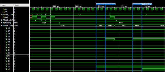
On the previous entry of this series we went through the VHDL source file and simulation of a Timer component. In this entry, we will instantiate several Timer components to create a timer bank (or block of timers). For this purpose we will instantiate the 'Timer' component presented on the first part of the tutorial several times. The instantiation is done inside a VHDL construct called a FOR GENERATE loop (see lines 50 - 61). The code is attached below: 1 2 3 4 5 6 7 8 9 10 11 12 13 14 15 16 17 18 19 20 21 22 23 24 25 26 27 28 29 30 31 32 33 34 35 36 37 38 39 40 41 42 43 44 45 46 47 48 49 50 51 52 53 54 55 56 57 58 59 60 61 62 library ieee ; use ieee.std_logic_1164.all ; use ieee.numeric_std.all ; use work.top_pack.all ; entity top_timer_blk is port ( clk : in std_logic ; rst : in std_logic ; -- inputs data_in : in std_logic_vector (DATA_W - 1 downto 0 ); -- Data bus, connected to all timers load :

High Speed Serial I/O - free book

Image
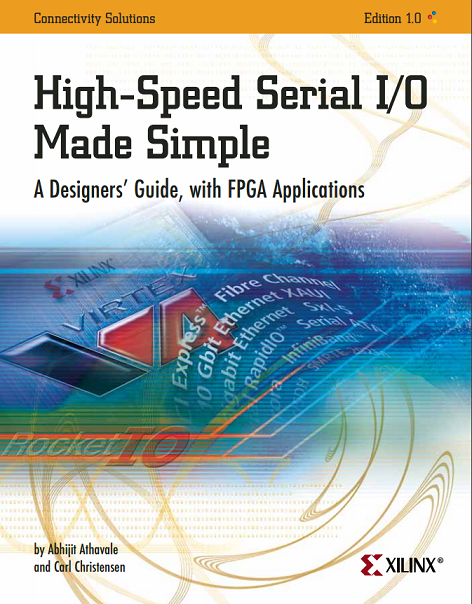
This post is now hosted here

SoC and MPSoC

Image
This post is now hosted here

Timers block

Image
Hi. In this series of articles, we will experiment with the definition, implementation, simulation and synthesis of a block of timers in VHDL. Along the way, we will: Test the VHDL code blocks using Vivado simulator. Synthesize and implement the VHDL code on Xilinx's Zynq FPGA. Originally this project was used on a relatively small FPGA. The logic for the timers didn't fit so I used the internal memory to implement the solution. In many of my designs I have seen that it is the LUTs (and not the FFs or the internal RAM) what tends to be under heavy utilization. So using the block RAM to implement register (or timers) banks can be a way to fit a design into a device. So first, let's start with the code for a single timer component: 1 2 3 4 5 6 7 8 9 10 11 12 13 14 15 16 17 18 19 20 21 22 23 24 25 26 27 28 29 30 31 32 33 34 35 36 37 38 39 40 41 42 43 44 45 46 47 48 library ieee ; use ieee.std_logic_1164.all ; use ieee.numeric_std.all ; entity

VHDL component vs. entity

Image
This post is now hosted here

Pseudo random number generator Tutorial - Part 3

Image
Matlab FFT of LFSR output On the first two chapters  of this Tutorial we started with a simple LFSR module and added a test bench. Then, on  chapters three and four  we upgraded our module with some features and learned to export the test bench data to files. Chapter 5 - Matlab Formal Verification Our VHDL block implements an algorithm that generates pseudo-random numbers. If the register is large enough, the output of the block will have hundreds or thousands of different numbers. How can we be sure that our block is working OK? For algorithms validation, Matlab comes as a very handy tool. First, we will generate an LFSR in Matlab which also creates a results file. Then we can just simply compare both files, if they are equal, we have an additional degree of confidence in our VHDL block. This is what the following Matlab code does: 1 2 3 4 5 6 7 8 9 10 11 12 13 14 15 16 17 18 19 20 % Generate LFSR a = uint32( 0 ); % Order of the polynom, up to 32 % Matl

The Zynq book (free)

Image
This post is now hosted here

FPGA Design flow summary

Image
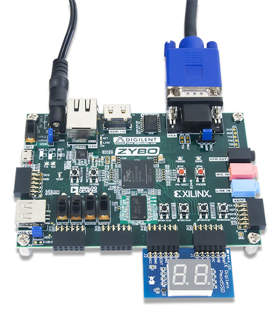
Zybo evaluation board - Source: Digilent This post is now hosted here

Pseudo random number generator Tutorial - Part 2

Image
This chapter of the tutorial is now hosted here Go to the third part of this tutorial

Prototypical – FPGA prototyping free book

This article is now hosted here

Signed, unsigned and std_logic_vector

This post is now hosted here

Analysis, elaboration and synthesis

Image
Do you recognize that feeling when you think you knew something, until somebody asks you to explain it? Well, that was what happened to me when I tried to explain what "Analysis and Elaboration" is. I used it in FPGA tools many times, and I had a certain "knowledge" of what it was, but, what are those processes EXACTLY? And, while we are at it, we will also describe what Synthesis is. Let's see: Analysis Analysis is the process where the design files are checked for syntactic and semantic errors. The syntactic rules are dictated by the language. On VHDL, if you write IF but forget to include the THEN clause, that is a violation of the  syntax , the set of rules of the VHDL language. Semantics are the meaning of the language. A sentence describing an addition is tagged as incorrect if the operands are of incompatible types and the VHDL compiler cannot resolve the meaning of that sentence. Elaboration VHDL designs are hierarchic by natur