Posts

Showing posts from May, 2017

Spartan 7 now available

"Xilinx announced today that its Spartan-7 family of FPGAs is now available for order and shipping to standard lead times. As a key member of Xilinx's Cost-Optimized Portfolio, this device family is designed to meet the needs of cost-sensitive markets by delivering low cost and low power entry points that are I/O optimized for connectivity with industry leading performance-per-watt" For more information: Spartan-7 general availability announcement Spartan-7 device page

Match rockets

Image

Introduction to Verilog

Image
This page is now hosted here

DTMF encoding and decoding

Image
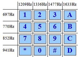
Dual Tone Multi-Frequency (DTMF) is a method for encoding and decoding up to sixteen digits and special characters to be sent over a voice channel. DTMF was first developed by Bell Systems in United States, for use in push-button dialing telephones (in constrant to prior phones, which had a mechanic rotary dialing system). DTMF is standardized by ITU-T Recommendation Q.23 A DTMF keypad consists of a matrix of sixteen push buttons organized in four rows by four columns. Each button, when pressed, generates a pair of tones. The tones belong to two groups, a low frequency group (697 to 941 Hz) and a high frequency group (1209 to 1633 Hz). On the picture below you can see the buttons and associated frequencies: Pressing an '8' generates two tones, one low frequency tone of 852 Hz and one high frequency tone of 1336Hz. The frequencies were selected so no one would be an harmonic of another DTMF frequency. As it usually is for many digital transmission systems, the enc

Timers block - Part three

Image
In the first part of this tutorial , we commented about the implementation of a single timer. The second part presented the implementation of a register based timers block, In this (third) part of the tutorial we will see a different way to implement the timers block. The timers block is a rather thirsty animal, let's see how many resources it needs for several configurations: Quantity of LUT Quantity of FF Single 32 bit timer 43 33 16 x 32 bit timers block 704 528 32 x 32 bit timers block 1,408 1,056 32 x 64 bit timers block 2,848 2,080 These numbers can be obtained by changing the DATA_W and TIMERS parameters on the VHDL package file and running synthesis for each configuration. After synthesis, in Vivado, we can get the number of used resources by taking a look at "Report utilization&q

FPGA internal tri-state buses

Image
Block RAM memory - Source: Xilinx This post is now hosted here